Table of Contents
Overview
The kobuki driver communicates with the robot by using predefined protocol. In general, the driver sends the commands to the robot and the robot sends some feedback data or sensor readings. These commands and feedback data are converted into bytestreams for communication via serial interface. The protocol specifies that rules and forms of bytestreams.
Structure of Bytestream
A bytestream can be divided into 4 fields; Headers, Length, Payload and Checksum.
| Name | Header 0 | Header 1 | Length | Payload | Checksum |
|---|---|---|---|---|---|
| Size | 1 Byte | 1 Byte | 1 Byte | N Bytes | 1 Byte |
| Description | 0xAA (Fixed) | 0x55 (Fixed) | Size of payload in bytes | Described below | XOR'ed value of every bytes of bytesream except headers |
Header
Two bytes of headers, header 0 and header 1, are fixed value for both bytestreams, commands and feedback data. This headers are used to detect the starting point of bytestream.
Length
Length indicates the length of following bytes that single bytestream hold. Default size of this field is 1 byte. Length can be used to distinguish each bytestreams. Minimum value of this field is 3.
Payload
Payload contains actual data of bytestream.
Structure Of Payload
- Payload is a consist of several sub-payloads.
Payload Sub-Payload 0 Sub-Payload 1 Sub-Payload 2 ... Sub-Payload N-1
Structure Of Sub-Payloads
- Sub-payload can be divided into three parts; Header, Length and Data.
Name Header Length Data Size 1 Byte 1 Byte N Byte(s) Description Predefined Identifier Size of data in byte(s) Described below
Checksum
Checksum is XOR'ed value of entire bytestream except headers. Checksum process ensure the integrity of bytestreams.
Here is simple code snippet for it.
Entire Bytestream
| Headers | Length | Payload | Checksum | |||||
| Header 0 | Header 1 | Sub-Payload 0 | Sub-Payload 1 | Sub-Payload 2 | ... | Sub-Payload N-1 | ||
Above table shows the structure of entire bytestream.
Minimum length of payload is 3; Payload with a sub-payload, that has only 1 byte data.
Theoretical minimum length of entire packet(bytestream) is 7.
Data Types
Data field in Sub-payload is a mixture of below three data types; byte, short and int.
| Name | Description | Byte Length | Bit Length | Data Range | C/C++ Identifier | |
|---|---|---|---|---|---|---|
| Unsigned Byte | 8-bit unsigned integer | 1 | 8 | 0~255 | unsigned char | uint8_t |
| Unsigned Short | 16-bit unsigned integer | 2 | 16 | 0~65,535 | unsigned short | uint16_t |
| Unsigned Int | 32-bit unsigned integer | 4 | 32 | 0~4,294,967,295 | unsigned int | uint32_t |
Serialization-Deserialization
Serialization is the process of converting a data structure into a bytestream. Deserialization is reversal process. Each data types are serialized and deserialized by <a href="http://en.wikipedia.org/wiki/Least_significant_byte">LSB</a>-First Order. It means Least Significant Bytes will comes first on the bytestream. For example, The integer number 2,864,434,397(0xAABBCCDD) can be serialized into:
| 0xDD | 0xCC | 0xBB | 0xAA |
So, 0xDD will arrive first in bytestream.
Here are template functions to handle it on kobuki_deriver, buildVariable() and buildBytes().
Command Packets
Command Identifier
| ID | Name | Description |
|---|---|---|
| 1 | Base Control | Control wheel motors |
| 2 | Reserved | |
| 3 | Sound | Play custom sounds |
| 4 | Sound Sequence | Play predefined sounds |
| 5 | Reserved | |
| 6 | Reserved | |
| 7 | Reserved | |
| 8 | Reserved | |
| 9 | Request Extra | Request extra informations |
| 10 | Reserved | |
| 11 | Reserved | |
| 12 | General Purpose Output | Control general purpose outputs |
| 13 | Set Controller Gain | Set PID gain of wheel velocity controller |
| 14 | Get Controller Gain | Request current PID gain of wheel velocity controller |
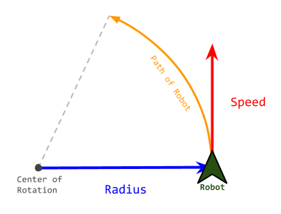
Base Control
Control wheel motors to moving robot. Robot will follow the arc line, which radius is <Radius> mm, with <Speed> mm/s. Positive Radius indicates center of arc line that robot follows is located at the left side of the robot. Negative is opposite.
But actual value of Speed field is little bit different. Here is conversion table.
| Motion | Speed(mm/s) | Radius(mm) |
|---|---|---|
| Pure Translation | Speed | 0 |
| Pure Rotation | wi) * bii) / 2 | 1 |
| Translation + Rotation | Speed * ( Radius + bii) / 2 ) / Radius, if Radius > 1 Speed * ( Radius - bii) / 2 ) / Radius, if Radius < -1 | Radius |
i) w is rotation speed of the robot, in [rad/s].
ii) b is bias or wheelbase, that indicates the length between the center of the wheels. Fixed at 230 mm.
| Name | Size | Value | Value in Hex | Description | |
|---|---|---|---|---|---|
| Header | Identifier | 1 | 1 | 0x01 | Fixed |
| Length | Size of data field | 1 | 4 | 0x04 | Fixed |
| Data | Speed | 2 | in mm/s | ||
| Radius | 2 | in mm |
Sound
Play custom sounds with note and duration.
| Name | Size | Value | Value in Hex | Description | |
|---|---|---|---|---|---|
| Header | Identifier | 1 | 3 | 0x03 | Fixed |
| Length | Size of data field | 1 | 3 | 0x03 | Fixed |
| Data | Note | 2 |  , where , where  is frequency of sound in Hz, and is frequency of sound in Hz, and  is 0.00000275 is 0.00000275 | ||
| Duration | 1 | Duration of playing note in milli-seconds |
- Warning
- This command is implemented on the kobuki with firmware, but not implemented yet on driver software(kobuki_driver).
Sound Sequence
Play predefined sounds by its index.
| Name | Size | Value | Value in Hex | Description | |
|---|---|---|---|---|---|
| Header | Identifier | 1 | 4 | 0x04 | Fixed |
| Length | Size of data field | 1 | 1 | 0x01 | Fixed |
| Data | Sequence number | 1 | 0 for ON sound 1 for OFF sound 2 for RECHARGE sound 3 for BUTTON sound 4 for ERROR sound 5 for CLEANINGSTART sound 6 for CLEANINGEND sound |
Request Extra
Request extra data from robot. Especially version info of kobuki; Hardware Version, Firmware Version and Unique Device IDentifier(UDID)
UDID is unique to device. so can be used to identify on multiple robots.
| Name | Size | Value | Value in Hex | Description | |
|---|---|---|---|---|---|
| Header | Identifier | 1 | 9 | 0x09 | Fixed |
| Length | Size of data field | 1 | 2 | 0x02 | Fixed |
| Data | Request flags | 2 | Set the flags to request extra data 0x01 for Hardware Version 0x02 for Firmware Version 0x08 for Unique Device ID |
General Purpose Output
This command has multiple roles. It controls LEDs, digital outputs and external powers.
| Name | Size | Value | Value in Hex | Description | |
|---|---|---|---|---|---|
| Header | Identifier | 1 | 12 | 0x0C | Fixed |
| Length | Size of data field | 1 | 2 | 0x02 | Fixed |
| Data | Digital output flags | 2 | Set the flags to set high on output pins of expansion port 0x0001 for digital output ch. 0 0x0002 for digital output ch. 1 0x0004 for digital output ch. 2 0x0008 for digital output ch. 3 Set the flags to turn on external powers 0x0010 for external power 3.3V ch. 0x0020 for external power 5V ch. 0x0040 for external power 12V/5A ch. 0x0080 for external power 12V/1.5A ch. Set the flags to turn on LEDs 0x0100 for red colour of LED1 0x0200 for green colour of LED1 0x0400 for red colour of LED2 0x0800 for green colour of LED2 |
Set Controller Gain
Set PID gain of wheel velocity controller of robot.
| Name | Size | Value | Value in Hex | Description | |
|---|---|---|---|---|---|
| Header | Identifier | 1 | 1 | 0x01 | Fixed |
| Length | Size of data field | 1 | 13 | 0x0D | Fixed |
| Data | Type | 1 | 0 for factory-default PID gain 1 for user-configured PID gain | ||
| P gain | 4 | Kp * 1000 (default: 100*1000) | |||
| I gain | 4 | Ki * 1000 (default: 0.1*1000) | |||
| D gain | 4 | Kd * 1000 (default: 2*1000) |
Get Controller Gain
Request PID gain of wheel velocity controller of robot.
| Name | Size | Value | Value in Hex | Description | |
|---|---|---|---|---|---|
| Header | Identifier | 1 | 1 | 0x01 | Fixed |
| Length | Size of data field | 1 | 14 | 0x0E | Fixed |
| Data | unused | 1 |
Feedback Packets
Feedback Identifier
Kobuki sends below default feedbacks periodically in 50 Hz, when it powered on.
| ID | Name | Description | Availability |
|---|---|---|---|
| 1 | Basic Sensor Data | Basic core sensor data | By default |
| 2 | Reserved | ||
| 3 | Docking IR | Signals from docking station | By default |
| 4 | Inertial Sensor | Gyro data both angle and angular velocity | By default |
| 5 | Cliff | PSD data facing floor | By default |
| 6 | Current | Current of wheel motors | By default |
| 7 | Reserved | ||
| 8 | Reserved | ||
| 9 | Reserved | ||
| 10 | Hardware Version | Version number of kobuki hardware | On request |
| 11 | Firmware Version | Version number of kobuki firmware | On request |
| 12 | Reserved | ||
| 13 | Raw data of 3-axis gyro | Raw ADC data of digital 3-axis gyro | By default |
| 14 | Reserved | ||
| 15 | Reserved | ||
| 16 | General Purpose Input | Inputs from 25-pin expansion port | By default |
| 17 | Reserved | ||
| 18 | Reserved | ||
| 19 | Unique Device IDentifier(UDID) | Unique number to identify robot | On request |
| 20 | Reserved | ||
| 21 | Controller Info | PID gain values of wheel velocity controller. | On request |
Basic Sensor Data
Basic core sensor data.
| Name | Size | Value | Value in Hex | Description | |
|---|---|---|---|---|---|
| Header | Feedback Identifier | 1 | 1 | 0x01 | Fixed |
| Length | Size of data field | 1 | 15 | 0x0F | Fixed |
| Data | Timestamp | 2 | Timestamp generated internally in milliseconds It circulates from 0 to 65535 | ||
| Bumper | 1 | Flag will be setted when bumper is pressed 0x01 for right bumper 0x02 for central bumper 0x04 for left bumper | |||
| Wheel drop | 1 | Flag will be setted when wheel is dropped 0x01 for right wheel 0x02 for left wheel | |||
| Cliff | 1 | Flag will be setted when cliff is detected 0x01 for right cliff sensor 0x02 for central cliff sensor 0x04 for left cliff sensor | |||
| Left encoder | 2 | Accumulated encoder data of left and right wheels in ticks Increments of this value means forward direction It circulates from 0 to 65535 | |||
| Right encoder | 2 | ||||
| Left PWM | 1 | PWM value that applied to left and right wheel motor This data should be converted signed type to represent correctly Negative sign indicates backward direction | |||
| Right PWM | 1 | ||||
| Button | 1 | Flag will be setted when button is pressed 0x01 for Button 0 0x02 for Button 1 0x04 for Button 2 | |||
| Charger | 1 | 0 for DISCHARGING state 2 for DOCKING_CHARGED state 6 for DOCKING_CHARGING state 18 for ADAPTER_CHARGED state 22 for ADAPTER_CHARGING state | |||
| Battery | 1 | Voltage of battery in 0.1 V Typically 16.7 V when fully charged | |||
| Overcurrent flags | 1 | Flag will be setted when overcurrent is detected 0x01 for left wheel 0x02 for right wheel |
- Note
- This sub-payload will be sent by default.
- See also
- Appendix : Kobuki Parameters - necessary parameters for conversion of encoder ticks to robot pose.
Docking IR
Signals from the docking station.
| Name | Size | Value | Value in Hex | Description | |
|---|---|---|---|---|---|
| Header | Identifier | 1 | 3 | 0x03 | Fixed |
| Length | Size of data field | 1 | 3 | 0x03 | Fixed |
| Data | Right signal | 1 | Flag will be setted when signal is detected 0x01 for NEAR_LEFT state 0x02 for NEAR_CENTER state 0x04 for NEAR_RIGHT state 0x08 for FAR_CENTER state ox10 for FAR_LEFT state 0x20 for FAR_RIGHT state | ||
| Central signal | 1 | ||||
| Left signal | 1 |
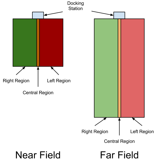
Kobuki's docking station has 3 IR emitters. The emitted IR lights cover three regions in front of the docking station: left, central and right, each divided in two sub-fields: near and far. Each beam encodes this information, so the robot knows at any moment in which region and sub-field he is. Also, as regions and fields are independently identified, they can be overlap on its borders.
Inertial Sensor Data
Inertial sensor data. Z-axis gyro data only available.
| Name | Size | Value | Value in Hex | Description | |
|---|---|---|---|---|---|
| Header | Identifier | 1 | 4 | 0x04 | Fixed |
| Length | Size of data field | 1 | 7 | 0x07 | Fixed |
| Data | Angle | 2 | Factory calibrated | ||
| Angle rate | 2 | Factory calibrated | |||
| Unused | 1 | ||||
| Unused | 1 | ||||
| Unused | 1 |
- Note
- This sub-payload will be sent by default.
Cliff Sensor Data
This sub-payload provides ADC data of PSD sensor, which is facing the floor.
This value is related with distance between sensor and floor surface. See the datasheet for more detailed information.
This data also available in the Cliff field of Basic Sensor Data , as a boolean type, processed on the kobuki.
| Name | Size | Value | Value in Hex | Description | |
|---|---|---|---|---|---|
| Header | Identifier | 1 | 5 | 0x05 | Fixed |
| Length | Size of data field | 1 | 6 | 0x06 | Fixed |
| Data | Right cliff sensor | 2 | ADC output of each PSD Data range: 0 ~ 4095 (0 ~ 3.3V) Distance range: 2 ~ 15 cm Distance is not linear w.r.t. ADC output. See the datasheet for more detail. | ||
| Central cliff sensor | 2 | ||||
| Left cliff sensor | 2 |
- Note
- This sub-payload will be sent by default.
- See also
- Basic Sensor Data
Current
Current sensor readings of wheel motors.
| Name | Size | Value | Value in Hex | Description | |
|---|---|---|---|---|---|
| Header | Identifier | 1 | 6 | 0x06 | Fixed |
| Length | Size of data field | 1 | 2 | 0x02 | Fixed |
| Data | Left motor | 2 | in 10mA | ||
| Right motor | 2 | in 10mA |
- Note
- This sub-payload will be sent by default.
Hardware Version
Hardware version info in triplet form; <major>.<minor>.<patch>
| Name | Size | Value | Value in Hex | Description | |
|---|---|---|---|---|---|
| Header | Identifier | 1 | 10 | 0x0A | Fixed |
| Length | Size of data field | 1 | 4 | 0x04 | Fixed |
| Data | Patch | 1 | |||
| Minor | 1 | ||||
| Major | 1 | ||||
| Unused | 1 | 0 | 0x00 | Fixed |
- Note
- This sub-payload will be sent on request.
- See also
- Request Extra
Firmware Version
Firmware version info in triplet form; <major>.<minor>.<patch>
| Name | Size | Value | Value in Hex | Description | |
|---|---|---|---|---|---|
| Header | Identifier | 1 | 11 | 0x0B | Fixed |
| Length | Size of data field | 1 | 4 | 0x04 | Fixed |
| Data | Patch | 1 | |||
| Minor | 1 | ||||
| Major | 1 | ||||
| Unused | 1 | 0 | 0x00 | Fixed |
- Note
- This sub-payload will be sent on request.
- See also
- Request Extra
Raw Data Of 3D Gyro
Raw ADC data of digital 3D gyro; L3G4200D
Due to difference of acquisition rate and update rate, 2-3 data will be arrived at once.
Digit to deg/s ratio is 0.00875, it comes from datasheet of 3d gyro.
| Name | Size | Value | Value in Hex | Description | ||
|---|---|---|---|---|---|---|
| Header | Identifier | 1 | 13 | 0x0D | Fixed | |
| Length | Size of data field | 1 | 2+6N | |||
| Data | Frame id | 1 | Frame id of 'Raw gyro data 0' Every sensor readings can identified by frame id , It circulate from 0 to 255 | |||
| Followed data length | 1 | 3N | ||||
| Raw gyro data 0 | x-axis | 2 | ADC output of each-axis in 0.00875 deg/s | |||
| y-axis | 2 | |||||
| z-axis | 2 | |||||
| : : | ||||||
| Raw gyro data N-1 | x-axis | 2 | ||||
| y-axis | 2 | |||||
| z-axis | 2 | |||||
- Note
- This sub-payload will be sent by default.
- Warning
- Sensing axis of 3d gyro is not match with robot. It is rotated 90 degree counterclockwise about z-axis. So, below conversion will needed. const double digit_to_dps = 0.00875;angular_velocity.x = -digit_to_dps * (short)raw_gyro_data.y;angular_velocity.y = digit_to_dps * (short)raw_gyro_data.x;angular_velocity.z = digit_to_dps * (short)raw_gyro_data.z;
General Purpose Input
| Name | Size | Value | Value in Hex | Description | |
|---|---|---|---|---|---|
| Header | Identifier | 1 | 16 | 0x10 | Fixed |
| Length | Size of data field | 1 | 16 | 0x10 | Fixed |
| Data | Digital input | 2 | Flag will be setted, when high voltage is applied 0x01 for digital input ch. 0 0x02 for digital input ch. 1 0x04 for digital input ch. 2 0x08 for input output ch. 3 | ||
| Analog input ch.0 | 2 | 12-bit ADC output of each channel Data range: 0 ~ 4095(2^12-1) Voltage range: 0 ~ 3.3 V | |||
| Analog input ch.1 | 2 | ||||
| Analog input ch.2 | 2 | ||||
| Analog input ch.3 | 2 | ||||
| Unused | 2 | ||||
| Unused | 2 | ||||
| Unused | 2 |
- Note
- This sub-payload will be sent by default.
Unique Device IDentifier(UDID)
Contains Unique Device IDentifier of robot. This value is unique for all robot in the world. It can be represented by triplet form: <UDID0>-<UDID1>-<UDID2>
| Name | Size | Value | Value in Hex | Description | |
|---|---|---|---|---|---|
| Header | Identifier | 1 | 19 | 0x13 | Fixed |
| Length | Size of data field | 1 | 12 | 0x0C | Fixed |
| Data | UDID0 | 4 | |||
| UDID1 | 4 | ||||
| UDID2 | 4 |
- Note
- This sub-payload will be sent on request.
- See also
- Request Extra
Controller Info
Contains PID gain of wheel velocity controller of robot.
| Name | Size | Value | Value in Hex | Description | |
|---|---|---|---|---|---|
| Header | Identifier | 1 | 1 | 0x01 | Fixed |
| Length | Size of data field | 1 | 21 | 0x15 | Fixed |
| Data | Type | 1 | Current controller setup 0 for factory-default PID gain 1 for user-configured PID gain | ||
| P gain | 4 | Kp * 1000 (default: 100*1000) | |||
| I gain | 4 | Ki * 1000 (default: 0.1*1000) | |||
| D gain | 4 | Kd * 1000 (default: 2*1000) |